Lab 1: Microcontroller
Objectives
- Learn how to use the various functionalities of the Arduino Uno, the Arduino IDE and GitHub.
- Construct a simple functional Arduino program using multiple external components and the Arduino Uno.
- Assemble our robot and have it perform a simple autonomous task
Subteams
Team 1: Manhal, Grant
Team 2: Jason, Beau
Blinking an internal LED
After downloading the Arduino IDE from this link, we used the Blink example that can be accessed from File»Examples»01.Basics»Blink to successfully blink the internal LED.
Blinking an external LED
We connected the ouptput pin 12 of the Arduino with the LED, in series with a 1.2 kΩ resistor. The longer leg of the LED is the positive lead (anode) and should be connected with the resistor (and thereby pin 12). The shorter, negative side should connect to GND of the arduino. The setup is shown in the picture below:
We then modified the existing Blink code to blink an external LED by setting the output pin to the external pin (pin 12) rather than the built-in LED (defined as LED_BUILTIN) in setup() as follows:
int pinnumber=12;
void setup() {
//used to initialize digital output pin as pin 12
pinMode(pinnumber, OUTPUT);
}
We then write to pin 12 as follows:
void loop() {
  digitalWrite(pinnumber, HIGH);   // turn the LED on (HIGH is the voltage level)
}
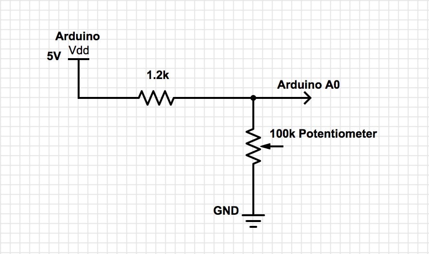
Reading the value of a potentiometer via the serial port
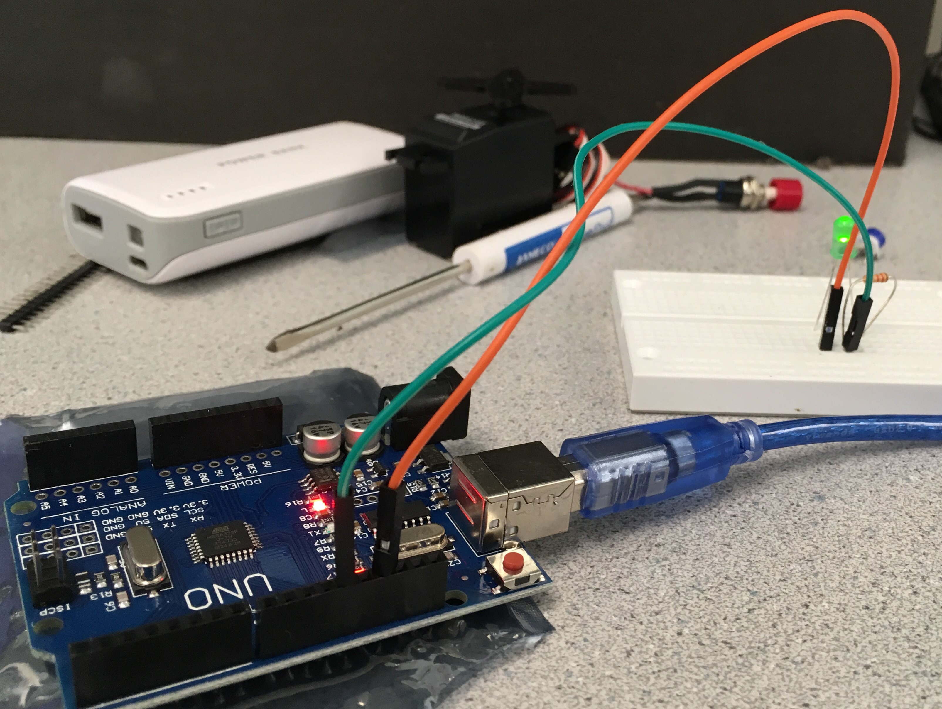
The following diagram shows the connection of the potentiometer to the Arduino.
To read the analog value from the potentiometer, we first had to initialize the serial communication over USB by including the following code in setup():
Serial.begin(9600); // sets the data rate in bits per second (baud) for serial communication
In our loop(), we read the sensor value from pin 0 on the Arduino and and print it on the serial monitor using the following code:
float value=analogRead(A0); //read the value from the potentiometer and assign it to var value
Serial.println(value); // print the value to serial port in ASCII text.
We also include a delay in our loop to print the value every .5 seconds by adding
delay(500); //delay the loop by 500ms
Uploading and running the sketch on the Arduino and printing the analog values on the serial monitor worked as expected. Here is a video of the setup and the corresponding analog values:
Map the value of the potentiometer to the LED
By connecting the LED to a PWM (Pulse Width Modulation) enabled pin (pin 9) on the Arduino we were able to map the potentiometer value to the LED. The following diagram shows the modified setup:
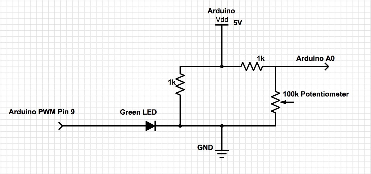
To map the potentiometer value to the LED, we first scaled the sensor value from 0-1014 to 0-255 since the maximum duty cycle (the pin output is always set to high) for 255. We used the following function:
int input=map(value, 0, 1014, 0, 255);
We then wrote the variable input to the PWM pin:
analogWrite(9, input);
The following is the implemented circuit from the schematic.
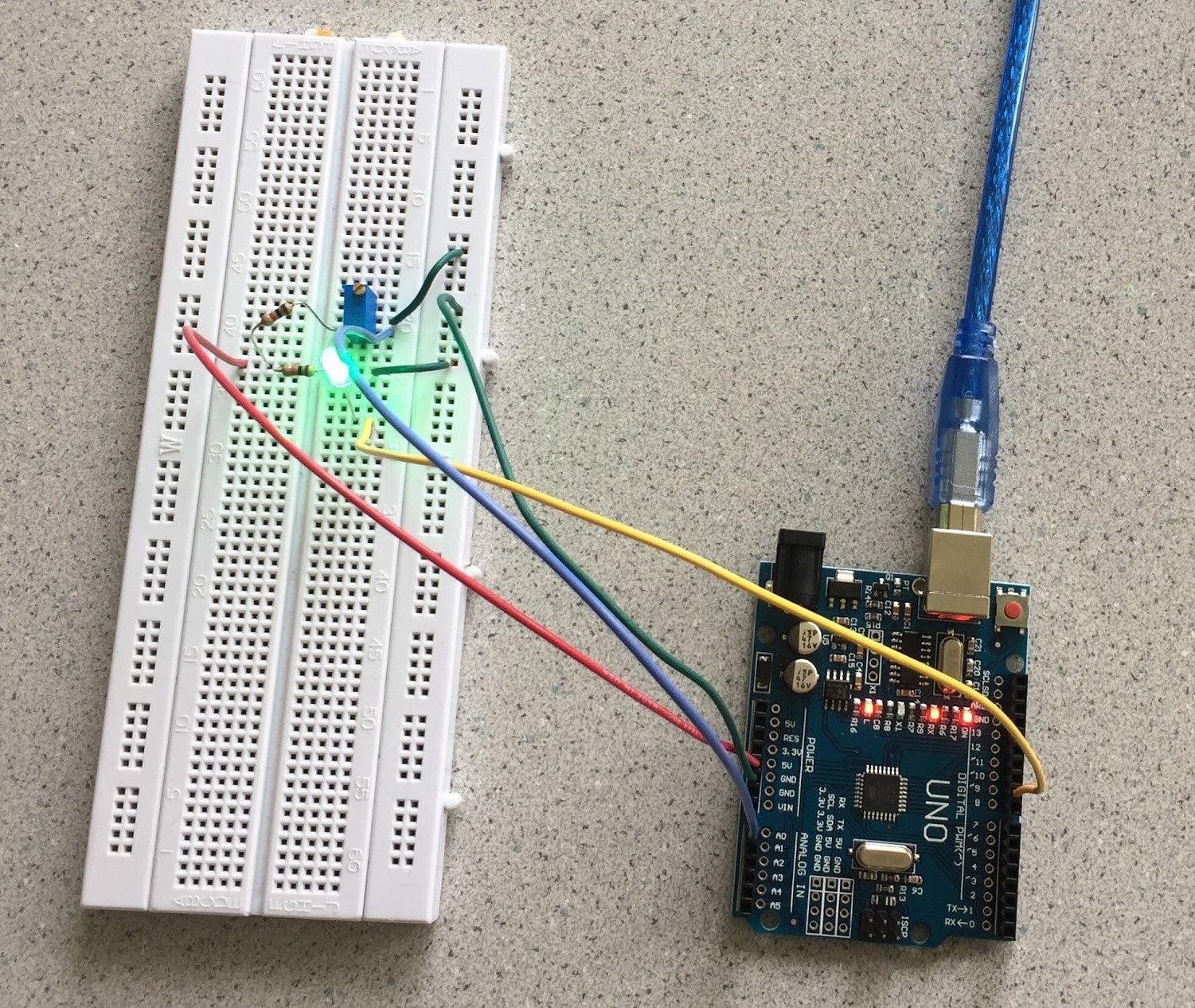
As we rotated the potentiometer, the LED changed brightness as shown in the following video:
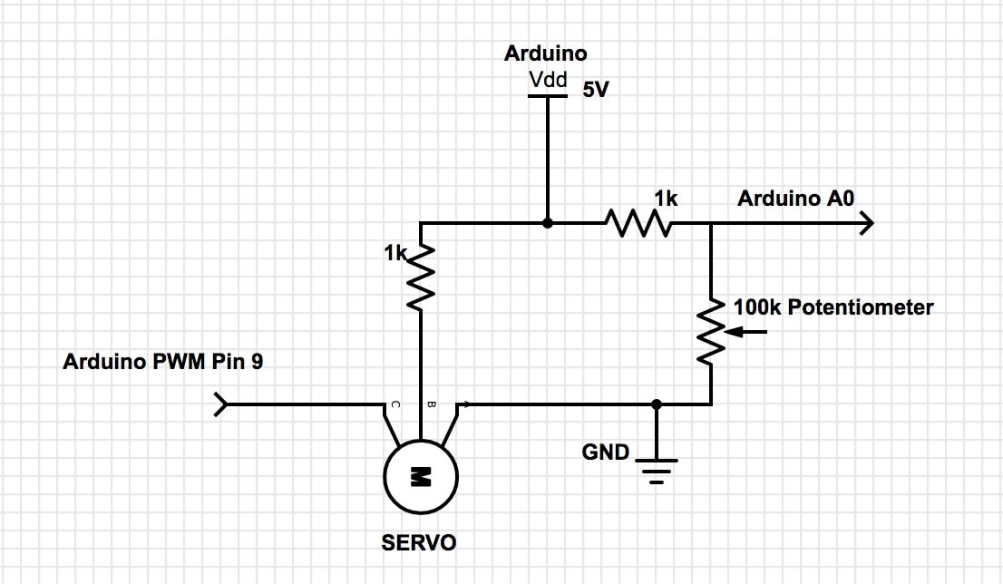
Map the value of the potentiometer to the servo
The Parallax Continuous Rotation Servos can rotate continuously over 360°. They take in PWM values between 0 and 180. If the value input is 90, the servo stops moving. At a value of 180, the servo is moving full speed in one direction, and at a value of 0 the servo is moving full speed in the opposite direction. Mapping the analog potentiometer values to the servo was done using a setup similar to the previous:
We first scaled 0-1014 to the Servo PWM range of 0-180 using the map function:
int input=map(value, 0, 1014, 0, 180);
Next, we wrote that value to the servo through pin 9 and added a 20ms delay to make sure the reading was correctly received:
myservo.write(input);   // adjusts the servo speed and direction based on the potentiometer value
delay(20);              // delay to ensure value is received by the servo
Below is a video of the servo’s response to a change in potentiometer values:
The duty cycle of the square wave corresponding to the PWM output is given by:
- 0:
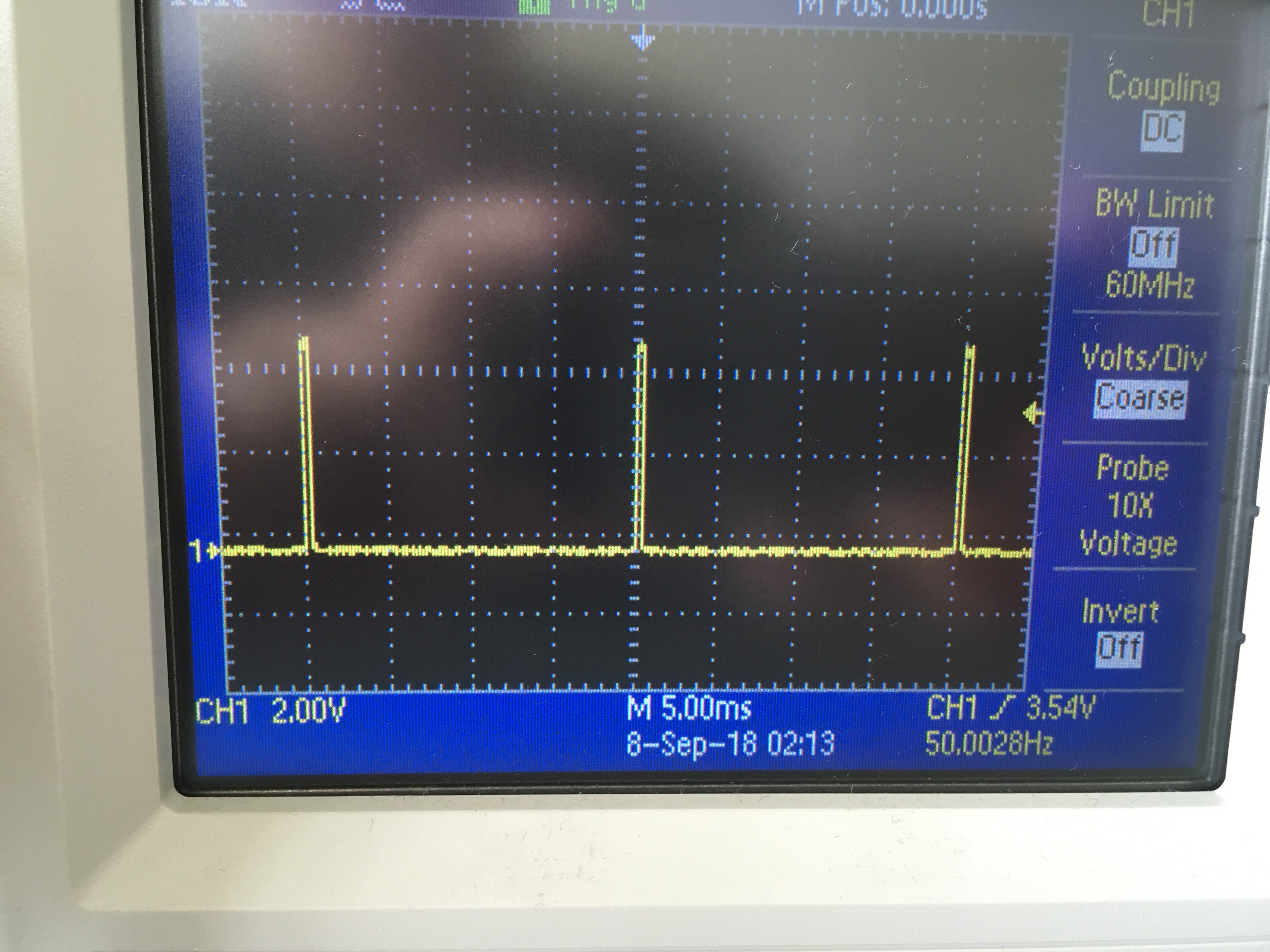
- 90:
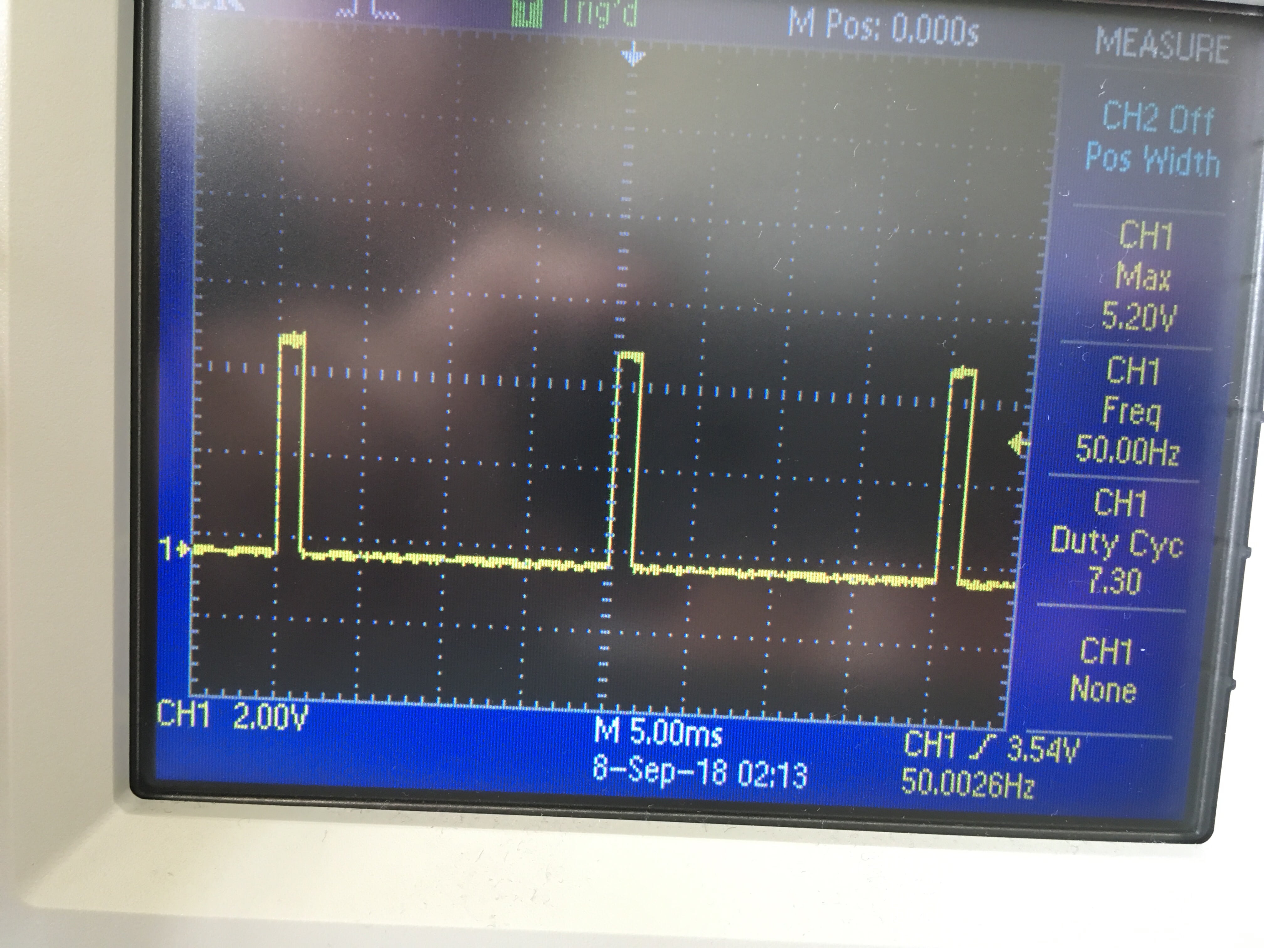
- 180:

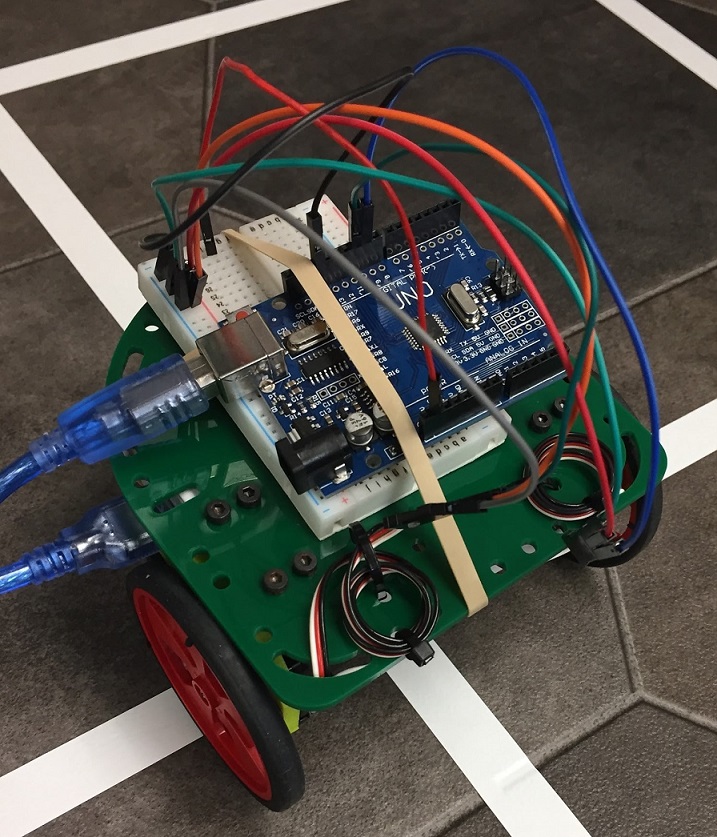
Assemble your robot
Looking at sample robots from past years, we assembled the necessary materials to construct the robot.

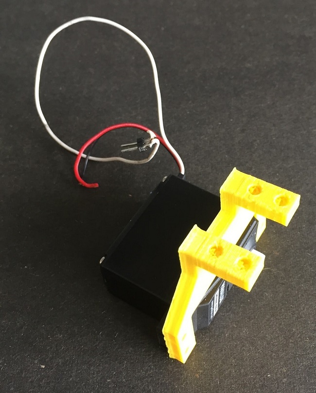
We then attached the two servos to mounts, and then attached the mounts to the main baseboard.
Afterwards, we attached wheels that fit well with the servos onto the robot.
We then attached the front wheel to the baseboard.
The Arduino and breadboard are currently bound to the top of our baseboard using rubber bands. The battery pack is placed beneath the baseboard.
Driving your robot autonomously
After assembling our robot, we programmed it to move forward, backward, turn right by 90 degrees, and turn left by 90 degrees. All of these actions were separated by a one second pause. The turning time for 90 degrees (referred to as duration in the code below) was found by guess and check method. The following code was used:
void loop() {
//move forward for 2s
 servo1.write(0);//clockwise
 servo2.write(180);//counterclockwise
 delay(2000);

//stop for 1s
 servo1.write(90);
 servo2.write(90);
 delay(1000);

//move back for 2s
 servo1.write(180);
 servo2.write(0);
 delay(2000);

//stop for 1s
 servo1.write(90);
 servo2.write(90);
 delay(1000);

//rotate clockwise for duration
 servo1.write(90);
 servo2.write(180);
 delay(duration);

//stop for 1s
 servo1.write(90);
 servo2.write(90);
 delay(1000);

//rotate counter-clockwise for duration
 servo2.write(90);
 servo1.write(0);
 delay(duration);
}
Here is a video of autonomous motion of the robot: